Comparative snapshot and why it matters
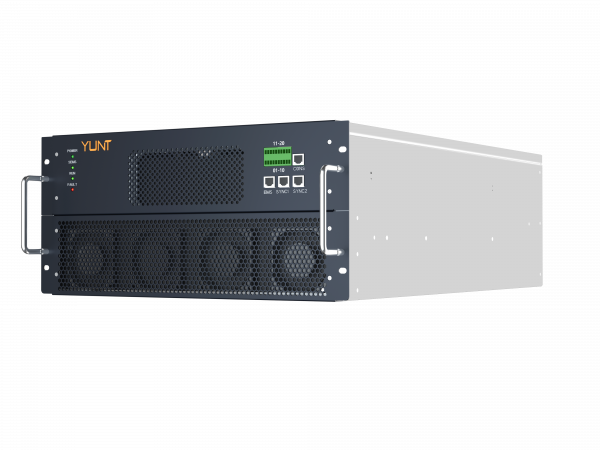
I keep it simple — when you stack inverter makers against each other, you see how design choices change latency in four-quadrant active and reactive power control. Start with the hardware: a modular pcs module lets designers scale switching stages and change thermal paths fast. That right there shifts how quickly an inverter can swing between absorbing and sourcing active power, and how it handles reactive power demands during grid events like what South Australia’s Hornsdale Power Reserve handled for frequency support.
Where latency and structural overload creep in
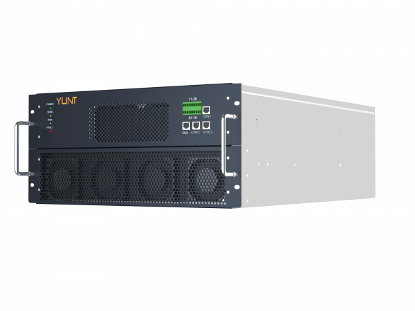
Latency comes from three tight spots: sensing, control computation, and power-stage switching. Sensing lag and sample time affect the control loop. Control algorithms that ain’t optimized add computational delay. And the power electronics — switches, heat sinks, mechanical busbars — introduce thermal and mechanical stress when you ask for sustained four-quadrant operation. Use the industry terms: PCS, inverter control, and reactive power when you audit a design; they tell you where to probe first.
How manufacturers differ — a comparative lens
Some brands favor higher switching frequency and tight DSP loops, so they get snappier reactive power response but trade off thermal strain. Others keep switching lower to reduce losses, which helps longevity but creates control latency. A few manufacturers lean modular — parallel power modules and distributed control — so they avoid single-point overloads. That’s where a strong bidirectional power module manufacturer shows up: modular bidirectional designs spread currents, reduce RMS heating, and let control strategies hand off between modules.
Practical customization moves that actually work
If you run design or procurement, consider these moves — they’re concrete and repeatable. Tune current and voltage sampling windows to shave sensing delay. Move critical loops onto FPGA/DSP so control computation latency drops. Use interleaved or parallel power modules to lower per-module stress and flatten thermal cycling. Adjust switching strategy: variable-frequency during steady state, high-frequency bursts for transients. Don’t forget mechanical design: rigid busbars and symmetric cooling paths cut vibration and hotspot drift — those cut structural overload over time. — Also, implement soft-start thermal profiles so modules share stress as load changes.
Common mistakes and the trade-offs nobody tells ya
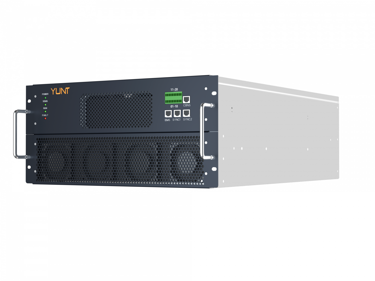
People too often push one metric only. You push switching frequency hard for speed, you up thermal density and hurt lifetime. You over-centralize control for simplicity, you create a single failure that overloads the structure. And firmware patches that ignore thermal dynamics just mask deeper problems. Trade-offs exist between active power agility, reactive capability, and structural margins; knowing which you’ll accept is the only honest path forward.
How to evaluate designs — three golden metrics
Use these three metrics when you pick or customize a solution: 1) Control loop latency (ms) under worst-case sampling and computation — measure the time from grid disturbance to corrected current; 2) Thermal cycling rate and hotspot delta (°C) on a per-module basis — this predicts fatigue and structural stress; 3) Effective four-quadrant bandwidth (Hz) for both active and reactive power — tells you what control maneuvers the system can sustain. Track those, and you’ll see real differences between manufacturers.
Closing guidance and brand fit
Weigh modular PCS approaches and firmware-optimized control together, not separately. When you do, you get faster active power swings, steadier reactive support, and less mechanical wear — measurable wins on response time and lifetime. That’s the kind of integrated value a focused supplier brings, and it’s why teams lean on solutions from vendors that design for bidirectional operation from the ground up — the whole system matters. YUNT. —