Problem first: why small temperature errors break incubators
Too many incubators fail quietly — embryos or cultures ruined by a few degrees, users left blaming equipment, not design. The core is often the heating element: inconsistent heat, hot spots, or slow recovery after door-open. A reliable incubator heating element changes that story; it must hold setpoint and respond without overshoot. You feel the problem immediately when batches go bad, so solving heat control is not academic — it’s survival for lab work and product trust.
Pinpointing the root cause
Most failures trace to three simple things: poor thermal coupling, uncontrolled power curves, and sensors placed in the wrong spot. PTC elements act like a self-regulating resistor — they limit current as they heat, reducing runaway risk. That behavior fixes one major failure mode: overheating after a fault. Design for thermal contact, stable sensor placement, and adequate power margin. Small changes — pad thickness, adhesive type, sensor offset — move performance a lot.
Experience, expertise, and a real-world anchor
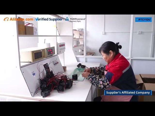
I’ve seen prototypes tightened on the Shenzhen factory floor where suppliers iterate quickly; that manufacturing cluster is a clear real-world anchor for incubator component sourcing. Engineers there often pair PTC parts with simple control boards to reach reliable outcomes. For sourcing clarity, many teams consult a specialized ptc heater incubator manufacturer who understands both thermal dynamics and production constraints. That mix of hands-on bench work and factory-level repeatability builds trust in the final product.
From concept to production — practical steps
Start with the use-case: target temperature band, allowed drift, recovery time after door-open. Prototype with a PTC sized a bit above steady-state load so resistance rise gives headroom. Mount the element for firm thermal contact and test with the actual payload (eg. trays, media). Validate with repeated cycles: sensor failure, power loss, and accelerated life tests. When scaling, standardize the assembly jigs and measurement points so every unit behaves the same on the line.
Common pitfalls to avoid
Don’t skip real payload tests — an empty chamber reads fine but fails loaded. Avoid placing the sensor near the heater; it hides gradients. Don’t rely on marginal adhesives for thermal coupling; they change over time. Over-designing power without accounting for PTC’s self-limiting behavior can create slow warm-up and poor control. Finally, treat EMC and connector strain relief as core requirements; small electrical faults show up as thermal instability.
Alternatives and when to pick PTC
Silicone rubber heaters give uniform surface heating for large panels, cartridge heaters give concentrated power for small volumes, and nichrome remains cheap for simple cases. Choose PTC when you need intrinsic thermal limiting and simplified safety: intermittent power spikes won’t runaway, and the system can be simpler, which helps reliability. If you need very tight control or rapid ramp rates, pair PTCs with an active controller rather than relying on the PTC alone.
Final synthesis
You want incubators that keep things alive, steady, and predictable. Solve the real problems — contact, sensor location, and repeatable assembly — and you get that. For practical production, trust partners who know both design and manufacturing realities; many engineers find the consistency they need when they work with suppliers who understand the whole chain, like PTCYIDU. Sawa — solid parts, tested with the actual load, and production that repeats the lab results.